Category Archives: Aircraft design

SIZING OF AIRCRAFT ACCORDING TO TAKEOFF DISTANCE REQUIREMENT

SIZING OF AIRCRAFT ACCORDING TO    TAKEOFF           DISTANCE REQUIREMENT

6

2

The take off ground run (STOG) of an aircraft is proportional to takeoff  wing loading (W/S)TO, or  take off power loading (W/P)TO . and maximum take off  lift CLmax  .

i.e,             STO a  ( (W/S)TO* (W/P)TO ) / (sCLmax) = TOP    ——-(1)

     this equals to TOP (take off parameter ) and its dimension  is  newton2/ m2hp .

As we know that the coefficient of lift at take off is typically 1.21 times maximum lift coefficient.

So we can write it as a CTO = CLmaxTO  / 1.21

Below Fig relates STOG to the  take off parameter . for a range of aircraft of single and twin engine (source by aircraft flight dynamics and automotive flight control , Roskam.).

4

This graph suggest following relationship

                     STOG  = 4.9 TOP +0.009TOP2               ———————(2)

And , fig  Below  implies that ,

3

STO = 1.66 STOG                               ————(3)

   NOW from above two equation we get,

                          STO = 8.134 TOP + 0.0149 TOP2         ———–(4)

THIS EQUATION are generated on the basis of data from FAR 23 aircraft.

For the calculation for jet aircraft we might replace (W/P) TO (W/T).

5

Here is one example so that the above concept will clear to everyone.

For a given aircraft (take propeller driven) it is specified that STOG LESS THAN 1000m and STO IS LESS THAN 1500m at an altitude of 5000 ft  in standard atmosphere.

Equation (3) stipulates that ,

STO < 1660m

This clearly violate the second requirement. So for both takeoff requirement to be met it is necessary that ,

1500 = 8.134TOP + 0.0149 TOP2

FROM this we get TOP = 145.6

Since s = 0.8616 at 5000 ft , now put this values in eq—-(1) it translate into ( (W/S)TO* (W/P)TO ) / (CLmax) < 145.6 *0.8616

Now by putting the values of  (CLmax)   and  (W/P)TO we get approximate value of (W/S)TO  

SIZING OF AIRCRAFT ACCORDING TO MANEUVARING REQUIREMENT

SIZING OF AIRCRAFT ACCORDING TO MANEUVARING REQUIREMENT

In this post I am going to introduce about the sizing of aircraft according to their maneuvering requirement .

Specific requirement for sustained maneuvering capability (including sometimes specific turn rate) are often contained in the mission specification for agricultural ,aerobatic or for military aircrafts.

Sustained maneuvering requirement are usually formulated in terms of a combination of sustained load factor (n) at some speed and altitude.

The sustained maneuvering capability of an aircraft depends strongly on its maximum lift coefficient and on its trust.

download

For equilibrium in vertical direction of flight , it Is necessary that:-

n*W =CL*q*S       ———–(1)

where n= load factor and, q= dynamic pressure

the maximum load factor can be capability of an aircraft (nmax)can be found from above equation(1) ;

nmax = CL*q /(W/S)

this load factor can be sustained as long as there is sufficient thrust, since:-

THRUST = DRAG

T= CDO + KCL2,

T= (q*CD0*S )+( CL2*q*S/∏e*A.R)

After dividing above equation by W  we get :-

T/W = (q*CDO/(W/S)) + (W/S)(nmax)2/(∏*e*A.R )

NOW,

If some maximum load factor is desired on a sustained basis at a given speed and altitude then , the above equation can be used to find out the relation between (T/W) and (W/S) for a given value of cd0.

so we can find out the wing loading for a specific thrust by weight ratio and hence design the wing /aircraft accordingly.

download (1)

If requirement is includes some specific turn rate then the following equation might be helpful:-

                            Turn rate= g(n2-1)1/2/V

EFFECT OF DIFFERENT LOCATION OF AIRCRAFT CENTER OF GRAVITY

EFFECT OF DIFFERENT LOCATION OF AIRCRAFT

                                               CENTER OF GRAVITY

In this post I am going to share my knowledge about the effect of  different locations of center of gravity(away from the margin specified by designer ) in different directions  , so that you can identify the probable cause in your model if your craft show below given character .


  1. 1.      IMPACT OF LONGITUDINAL  POSITION OF C.G

a)      When c.g is too forward

gg

  • When c.g is forword the elevator authority will decrease by large magin. This effect we can see at the time of landing and take off .
  • ON LANDING  aircraft is unable to pitch up at low speed , the aircraft is too nose heavy.
  • ON TAKE OFF  aircraft unable to produce enough moment to rotate the nose resulting aircraft need longer runway for taking off.


  • EFFECT ON LONGITUDINAL STABILITY :- The forword c.g location will increase aircraft longitudinal stability (why? Explanation below ).
  • The forward c.g has a greater distance to the neutral point, means greater the static margin, resulting better aircraft attitude after a disturbance due to gust .


  • PERFORMANCE VIEW. :- aircraft with forward c.g has very poor performance at any given airspeed (why ? reason below).
  • Due to too forward c.g the downward force on the tail to resist the nose drop tendency will increased ,it increased the trim angle of attack of the aircraft, resulting overall drag will increased.
  • Also Because o the above reason, the cruise speed for a given thrust and weight will reduced.

b)      When c.g is too aft

gg-1

  • Because of  too aft  c.g location , aircraft always have nose up tendency .and aircraft become more likely to stall(its too dangerous, believe me )
  • ON LANDING the effect is exactly opposite to the what  we see in forward c.g location i.e the more nose down elevator is required to counter the nose up tendency of aircraft.
  • ON TAKEOFF aircraft is likely to nose up prematurely , and reduced the climb performance  
  • Spin recovery becomes more difficult as the CG moves rearward. Reason:-Centrifugal forces acting about the CG, during a “flat” spin, pull the aircraft out of its axis of spinning, making it difficult to nose down and recover.


  • Possibility of a tip over if the CG is far aft the Neutral Point.

 2.     EFFECT OF LETERAL POSITION OF C.G

gg-3ggg-4

  • Laterally imbalanced c.g will cause unexpected roll during flight that required an extra effort to make the aircraft balanced .
  • It has little or no effect on longitudinal stability but affect the aircraft’s lateral stability.


  • The roll control surface (ailerons, spoilers ) sizing is extremely depends on the expected  variation of  lateral c.g that arise due to factors like weight asymmetry   , one side engine failure  etc.


  • The effect of lateral c.g imbalance on aircraft handling is typically assessed by:-

–          Fuel imbalance test

–          One engine failure test (for multiengine aircraft  ).


The combination  of both scenarios provides the maximum rolling moment for the aircraft that is crucial in aileron and spoilers sizing.

3.      EFFECT OF VERTICAL POSITION OF C.G

  • The vertical location of the CG changes the amount of dihedral effect (for more on dihedral effect follow my 22nd  JAN  post ). As the  vertical CG  moves lower, dihedral effect increases. This is caused by the center of lift and drag being further above the CG and having a longer moment arm.
  •  So, the same forces that change as sideslip changes (primarily sideforce, but also lift and drag) produce a larger moment about the CG of the aircraft. This is sometimes referred to as the pendulum effect.
  • On lateral stability – a c.g elevation leads to a deterioration of spiral stability, dutch roll and roll maneuverability.

AIRCRAFT WING TIP SHAPE

Aircraft wing tip shape

As I have introduced in last post about winglet (an wing tip device) . how it improves the aircraft stall characteristics , and also increases the effective span and effective aspect ratio of the wing.

SOME MORE POINT ABOUT WINGLET

The winglet is cambered and twisted so that the rotating vortex flow at the tip creat a lift force on the winglet that has forward component. This forward component act as a negative drag, reducing the total wng drag.

A properly designed winglet can potentially provide an effective span increase up to double that bought by adding the winglets height to the wing span.

Winglets provide the greatest benefit when the wing tip vortex is strong, so a low aspect ratio wing will see more advantages fram the use of winglet than an already  highly efficient high aspect ratio wing.

Now  here , I am going to discuss about the type of wing tip shape that affect the aerodynamics of aircraft and its advantages and disadvantages.

TYPES OF WING TIP DEVICES

  • End plates
  • Classic Winglet (Whitcomb)
  •  Blended Winglet
  • Hoerner Tips
  • Upswept and Drooped Tips
  •  Wing Grid
  •  Sail Tips
  • Spiroid Tips
  • Tip Turbines

1)      END PLATES

 wtd

  • End plates are most common and most effective type.
  • It work same as like T –tail.
  • Above fig shows how it affects the span and aspect ratio of wing.

2)      CLASSIC WINGLET (WHITCOMB

wtd-1WTA

  • It Defined by Whitcomb
  • The Upper winglet begins at the point of maximum  thickness of wing airfoil.
  •  It having a sweep same as In wing.
  • The Span of it(upper part) equals to the tip chord of the wing.
  • Its camber is generally higher  than wing.
  • Lower winglet contributes little to drag hence it often omitted.

3)      BLENDED WINGLET

wtd-2

  • Greatly reduces the adverse flow conditions at winglet junction.
  • The Blended Winglet incorporates a large radius and a smooth chord variation in the wing-to-winglet transition area. This allows optimum aerodynamic loading and avoids vortex concentrations that produce drag.
  • High AR blended winglet can be up to 60% more effective than a conventional winglet.
  • Most important parameter in design is the ratio of winglet high to wing span.
  • Blended Winglets enhance longitudinal and directional stability, thereby providing better handling in turbulent atmospheric conditions.

4)      HOERNER TIP

wtd-3wtd-4

  • this is a sharp edged wing tip with the upper surface continuing the upper surface of the wing.
  • The lower surface is “undercut” and canted approximately 30 deg to the horizontal. It may also be undercambered   (concave).
  • It is somewhat similar to conventional tip.


5)      UPSWEPT  AND DROOPERD TIP

wtd-5

  • Similar to Hoerner Tips but curve either up or down to increase  the wing’s effective span.
  • This effect is similar to that employed by endplates.

6)      WING GRIDS

 wtd-6,1

  •  The circulation is taken over by the wing grid along the chord of thE main wing.
  •  The segmented circulation is transferred to the end of the wing grid, increasing the far field vortex spacing.
  • The lift distribution on several winglets results in a reduction of the far field vortex energy.
  •  Induced drag is reduced by the wing grid up to 60%, that corresponds to span efficiencies of up to over 3.0, that means that total drag can be reduced up to 50% depending on velocity and design.
  •  The winggrid has two distinct operating regimes:

1) Below a critical angle of attack (above a specific design speed) span efficiency is between 2.0 and 3.0 with full wing grid effect.

2) Above a critical angle of attack (below a specific design speed) the effect of reduced induced drag fades out, the winggrid perates as a slit wing with very high stall resistance.

7)      SAIL TIP


  • Sail tip is defined by multiple high Aspect Ratio lifting elements at several dihedral angles.
  • This kind are more complex to design and analyze .


8)      SPIROID WING TIP

wtd-8wtd-7

  • Spiroid wing tip produces a reduction in induced drag, much like that of a winglet. However, its closed planform shape may make it possible to reduce local lift coefficient often a problem for winglets.
  • Extensive optimization is necessary.
  • The major concern with it is fluttering of tip.
  • It reduce fuel consumption by 6-10% as compared to conventional tip.

9)      TIP TURBINE

wtd-9

  • Reduce the strength of vortices.
  • Recover energy required to overcome the drag.
  • It is estimated that a similar system on  B747 would result in the recovery of 400hp(source).

IMPROVING AIRCRAFT STALL CHARACTERISTICS WITH FIXED DEVICES

IMPROVING AIRCRAFT STALL CHARACTERISTICS WITH  FIXED                                                                     DEVICES 

Stalls and Spins

Stalls and resulting spins have caused aircraft accidents since the beginning of flight. Even though airplanes have evolved to have better stall characteristics, stalls and spins continue to be a leading cause of accidents.

A stall occurs when airflow separates from all or part of the upper surface of a wing, resulting in sudden loss of lift. This is caused by exceeding the critical angle of attack (angle of attack is the angle between the relative wind and the chord line of the airfoil).SEE FIG.

STALL

Below the critical angle, airflow over the wing surface is relatively smooth. Above the critical angle, the thin layer of air above the wing, or “boundary layer,” becomes turbulent and separates from the airfoil  Lift is destroyed and drag increases, causing the aircraft to rapidly lose altitude. Pilots are trained to recover from this condition. However, if the stall occurs too low to the ground, there may not be enough altitude to recover.Stalls are usually associated with slow flight in a nose-up attitude, but they can occur at any airspeed or attitude.

STA5

FIG- aircraft under spin

Spins are of even greater concern because recovery requires more altitude and more actions on the part of the pilot. Simply stated, a spin is an autorotation resulting from one side of the wing stalling more than the other. Spins cause rapid loss of altitude. If the pilot does not recover, the aircraft will spin into the ground. Aircraft design affects the ease of entering and recovering from spins. Adding devices to improve stall characteristics will generally reduce spin-related accidents; preventing a stall or making it gentler can reduce accidental spins. Straight-wing aircraft must stall before they will spin (swept-wing aircraft do not necessarily have to stall first) .

Favorable Stall Characteristics

  • Aircraft are designed to have the most favorable stall characteristics possible given the compromises involved. A good aircraft should give the pilot adequate warning of the stall, stall gradually, and tend not to spin after the stall .
  • This means the aircraft wing should stall at the roots first, rather than at the tips where the ailerons are located. (Stalling at the tips first renders the ailerons ineffective for roll control.) Usually a NEGATIVE twist, or “washout,” is built into the wings so that the tips are always at a lower angle of attack. However, this is not always enough to create good stall characteristics. Some aircraft require further modifications to the wing.
  •  In the interest of safety, several types of fixed devices can modify a basic wing in order to improve stall characteristics. These include winglets, leading edge cuffs, stall strips, stall fences, slots, and vortex generators.

Winglets

sta-4

stall-2syta-3

Winglets, which are vertical extensions of the wingtips, improve stall characteristics by reducing induced drag. This induced drag comes from high pressure air under the wings flowing around the tips to the lower pressure area above, creating vortices. Winglets redistribute the intensity of wingtip vortices over a larger area. They increase the maximum coefficient of lift, resulting in a lower stall speed.

NASA studied the effect of winglets on the performance and handling qualities of aircraft. Using windtunnels, NASA tested two versions of a model airplane: one with winglets and one without. At stall, the airplane without winglets tended to “roll off” and “drop a wing”. The airplane with winglets demonstrated improved stall characteristics. According to a NASA report, “The winglets appeared to prevent the wing tip from stalling first… reducing the tendency to roll off” . In another study during the fuel crisis of the 1970s, NASA aerodynamicist Richard Whitcomb found that winglets reduced drag by 20 percent. Less drag means faster stall recovery.

Winglets have disadvantages that may outweigh their advantages in some cases. They create interference drag at the junction between the wing and winglet. This drag offsets the induced drag reduction. Winglets also have a tendency to flutter.

Leading Edge Cuffs

staj-6

  • Leading edge cuffs are extensions that project forward and droop from the outboard sections of an aircraft’s wings.
  • They divide a wing into two different airfoils. The outboard section, with the cuffs, has a lower angle of attack and continues flying while the inboard section stalls. This allows the ailerons to continue to be effective in the stall. Wing cuffs also increase the stalling angle of attack .

Cuff Creates a secondary vortex over the wing Prevents separated flow from propagating down the span Attached flow is maintained over the tip and aileron see fig below

staj-7

The disadvantages of leading edge cuffs are that they complicate the wing design and cannot be easily added to an existing wing.

Stall Strips

stal-8 sta-10

  • A simple way to make the inboard section of a wing stall first is to install a stall strip on the inboard leading edge.
  • Stall strips are lengths of wedge-shaped metal, wood, or other material that run parallel to the leading edge.
  •  At high angles of attack, the strips disrupt the boundary layer behind them and cause a stall in that area . They have the added benefit of causing a more pronounced stall buffet, providing more warning to the pilot.
  • Stall strips are very common, especially in homebuilt aircraft, because they are easily removed and reattached. Homebuilders can experiment by putting the strips in different locations and noting their effect on stall characteristics.
  •  Stall strips are also found on many production aircraft, such as the Mooney series and the Cirrus SR20 and SR22. Some aircraft use stall strips on only one wing in order to eliminate an asymmetric stalling pattern .

While stall strips often improve stall characteristics, they are not always a quick fix for an airplane with poor handling qualities.

Stall Fences

stal-11

  • Stall fences are another device to prevent wing tips from stalling before the roots.
  • They are thin plates which project up from the wing and lie parallel to the aircraft’s axis of symmetry. Without these fences, a spanwise airflow along wings causes the boundary layer to thicken toward the wingtips, especially on swept-wing aircraft. This results in early boundary layer separation at the wingtips and loss of aileron control.
  • Fences block spanwise airflow, preventing boundary layer buildup over the ailerons and thus improving stall characteristics .
  • Stall fences are primarily found on swept-wing aircraft like business jets and fighters, but are also found on straight-winged general aviation aircraft. The Eagle 150 has a unique design featuring a main wing, a forward wing, and a horizontal stabilizer. Each side of the main wing has a stall fence, which according to the manufacturer “redirects the airflow to the ailerons, creating a re-energizing effect. This allows the pilot or student pilot full control at minimum speed, and even at the point of stall” (Eagle Aircraft).

Some aircraft have aerodynamic stall fences. These are not the typical vertical plates, but instead other devices which create the same effect. The Questair Venture kitplane has a small vertical slot on the leading edge of each wing; the airplane looks like it ran into a bandsaw. At high angles of attack, air flowing through this slot creates a trailing vortex that acts like a stall fence .the  “rooster tail” of air creates turbulent, high pressure air that can “impede the spanwise advance of the stall” .

Whether the stall fence is a physical plate or an airflow barrier, this device combats the progression of a stall across a wing and helps keep air flowing over the ailerons.

Slots

stal-12

  • Fixed slots in aircraft wings are used to increase the maximum coefficient of lift and delay the stall.
  • Slots are long holes near the leading edge of a wing that run parallel to the leading edge. At high angles of attack, slots route high pressure air near the stagnation region under the wing to the lower pressure region on top . (This rerouted air energizes the boundary layer and delays its separation. Slots allow the aircraft to reach a higher angle of attack before stalling.
  • Slots greatly improve the performance of aircraft at high angles of attack, but they have disadvantages as well. They must be designed into the wing from the beginning; they cannot be retrofitted to improve a design.
  • ·         They cause a higher stall angle, so the plane must approach in a nose-up attitude that decreases visibility .
  •  The main disadvantage is that slots create excessive drag during normal cruising flight . (A solution to that problem is the slat, which is a slot with a moveable cover.

Vortex Generators

stL123 STA124

The most common boundary layer control devices are vortex generators. These are tiny plates mounted near the leading edge of the wing, perpendicular to the surface . Vortex generators energize the boundary layer by mixing in high-energy air from outside the boundary layer . They delay airflow separation .

Conclusion

The devices discussed in this section can help warn the pilot of a stall, cause the airplane to stall more gently, and make the airplane resist spinning. They are added measures of safety that improve a basic wing. Small changes in airflow patterns over a wing can greatly improve aircraft handling qualities at high angle of attack.


WING IN GROUND EFFECT


WING IN GROUND EFFECT

ge

The conventional practical use of lifting bodies, are wings on aircraft. In very broad terms, aircraft fly because the movement of the wing through the air produces a greater static pressure on the lower surface of the wing than on the upper surface of the wing. The pressure differential equates to a resultant force upward which supports the weight of the aircraft.

Aircraft normally fly in a freestream, that is the air around the wing is not bounded in any way.


WIG(wing in ground effect) craft make use of a phenomenon known as ‘ground effect’. Ground effect is the common name for the phenomenon where a boundary is placed below (and near) the lower surface of the wing. This results in an effective increase in the static pressure below the wing and increases the lift to drag ratio. In practice, the boundary is the earth’s surface, whether it is terrain or water.

  • When an aircraft is flying at an altitude that is approximately at or below the same distance as the aircraft’s wingspan or helicopter’s rotor diameter, there is, depending on airfoil and aircraft design, an often noticeable ground effect. This is caused primarily by the ground interrupting the wing tip vortices and downwash behind the wing. When a wing is flown very close to the ground, wingtip vortices are unable to form effectively due to the obstruction of the ground. The result is lower induced drag, which increases the speed and lift of the aircraft.


  • A wing generates lift, in part, due to the difference in air pressure gradients between the upper and lower wing surfaces. During normal flight, the upper wing surface experiences reduced static air pressure and the lower surface comparatively higher static air pressure. These air pressure differences also accelerate the mass of air downwards. Flying close to a surface increases air pressure on the lower wing surface, known as the “ram” or “cushion” effect, and thereby improves the aircraft lift-to-drag ratio. As the wing gets lower, the ground effect becomes more pronounced. While in the ground effect, the wing will require a lower angle of attack to produce the same amount of lift. If the angle of attack and velocity remain constant, an increase in the lift coefficient will result, which accounts for the “floating” effect. Ground effect will also alter thrust versus velocity, in that reducing induced drag will require less thrust to maintain the same velocity.
    •  Low winged aircraft are more affected by ground effect than high wing aircraft. Due to the change in up-wash, down-wash, and wingtip vortices there may be errors in the airspeed system while in ground effect due to changes in the local pressure at the static source.
    • Another important issue regarding ground effect is that the makeup of the surface directly affects the intensity; this is to say that a concrete or other smooth hard surface will produce more effect than water or broken ground.
    • When a wing approaches the ground two phenomena are actually involved in the increase of the lift force and reduction of the drag. The ground effect is a common name for both effects, which is sometimes confusing. These two phenomena are sometimes referred to as span dominated and chord dominated ground effect. The former results mainly in the reduction of the induced drag (D) and the latter in the increase of the lift (L). The designations span dominated and chord dominated are related to the the fact that the main parameter in the span dominated ground effect (reduces drag) is the height-to-span ratio ,whereas in the chord dominated ground effect (increases lift)it is the height-to-chord ratio.
    • an empirical formula has been derived for practical and preliminary calculations of the chord-dominate ground effect. It has the following form
    •               CLground = CL(h/c)-0.11

where CLground represents the wing lift coefficient in the ground effect mode,

CL – lift coefficient in open air, h indicates height of the wing and c is the chord length.

GROUND EFFECT

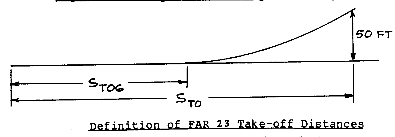
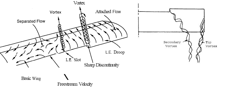
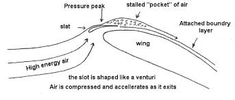
. Figure  depicts a wing in ground effect.

ge-6

The boundary creates an alteration of the flow field that is caused by the boundary not allowing the flow under the wing to expand as it would in free air. In terms of the total pressure of the flow, the additional lift is due to a rise in static pressure under the wing.

The total pressure of the flow field can be divided between the static pressure (surface pressure) and dynamic pressure (the pressure associated with velocity). As the total pressure remains constant throughout the flow field, the sum of the static and dynamic pressure must also remain constant.

As the flow is forced into the region between the wing and the boundary, the decrease in dynamic pressure is transformed into a rise in the static pressure. This rise in the Static pressure is often referred to as ‘ram pressure’. The resulting altered pressure distribution causes a net increase in the lift and a change to many of the other aerodynamic characteristics of the wing.

GROUND EFFECT’s Effect on lift ,drag, downwash

the boundary near the wing alters the flow field about the wing. The effect is

demonstrated in Figure

ge-2ge-3


The change in flow field has the effect of reducing the downwash angle and therefore increasing the effective angle of incidence at a given geometric angle of attack. This causes a corresponding rotation of the resultant force vector and changes to the component of lift an drag forces. The effect is to increase the lift component and reduce the induced drag component, thus increasing the lift to drag ratio.

The increased lift to drag ratio provides a net gain in efficiency and the reduction in drag provides the benefit of a reduced thrust requirement in cruise flight.

EFEECT ON PITCHING MOMENT

In addition to creating lift and drag, the movement of a wing through the air creates a moment about the aerodynamic centre of the wing. This moment is known as the pitching moment and is the result of the pressure distribution on the wings surface. In a moving craft this pitching moment needs to be balanced in order to keep the craft stable. WE typically add another lifting surface to overcome pitching moment, either at the rear of the aircraft (tailplane) or at the front of the aircraft (canard).

Ground effect alters the pitching moment generated by a wing. The altered flow about the wing moves the aerodynamic centre of the wing and therefore the pitching moment generated by the wing. The effect is the result of the pressure distribution changes over the lower surface of the wing. The ram pressure in extreme ground effect causes a near uniform pressure distribution over the under surface of the wing, while not significantly altering the upper surface pressure distribution (see Figure ).

ge-7

Wings generally create a nose down pitching moment in cruise flight. Ground effect causes an increase in this moment, resulting in a greater stabilizing force being required to balance the pitching moment. To remain stable, a craft in ground effect will generally require a larger tailplane or canard.

This larger surface creates greater drag and therefore reduces the efficiency of the craft as a whole. It also creates structural and weight penalties that reduce the efficiency of the craft.

An additional complication of pitching moment in ground effect is that the pitching moment changes with height above the boundary. In freestream flight, the aerodynamic centre is generally considered to be approximately one quarter of the chord back from the leading edge.

Flight in extreme ground effect may move the aerodynamic centre to the half chord position. This movement of the aerodynamic centre with the height of the wing above the boundary may cause considerable configuration design difficulties. In addition, the need to be able to control the craft over a large pitching moment range increases the drag, structural and weight penalties discussed earlier.

Considerable research has been Considerable research has been conducted into overcoming the variation of pitching moment with height. Many designers have claimed to overcome the effect by the use of unique wing sections and/or craft configurations. Different shaped wing sections should be able to limit this effect by altering the pressure distribution over the lower surface so the change from IGE(in ground effect) to OGE(out of ground effect) is not large. Such a section is the S-shaped section used on the Amphistar. However, these sections may be dramatically inefficient in OGE flight or incapable of operating OGE and this is a likely area for further research. Planform shapes differing from conventional aircraft may provide another method to reduce the change in pitching moment.

Effect of Height above the Ground

ge-5

From the modelling viewpoint, three separate models have emerged, each modelling a certain zone above the boundary.

The first zone is the region in which the wing is operating between the boundary and a height of 20% of the chord of the wing. This region has a high level of constriction of the flow in the vertical direction and the flow becomes two dimensional with the vertical degree of freedom of the flow is restrained.

The second zone is the region between the height of one chord length of the wing to ten span lengths. In this region, the model is dominated by the span of the wing. Inviscid flow models are used in this region and show a marginal increase in the L/D to that of OGE flight.

For awing flying in the region between 20% of the chord and one chord height, a combination of the two models are required. Above ten span lengths, free flight models currently used in aerodynamic theory for aircraft design, are used.

for wings operating in ground effect the addition of end plates is more efficient because they increase the lift to drag ratio more than if they where used to increase the wing’s span. It is also noted the end plates are more effective on wings of low aspect ratios, which are more likely to be found on WIG aircraft.

Theoretical Benefits of Ground Effect

ge-4

The theoretical efficiencies of airborne craft can be expressed in terms of their ability to carry a given payload over a given distance. This efficiency is directly related to the craft’s lift to drag ratio. WIG craft’s higher lift to drag ratio, provide them with the potential for greater efficiencies than aircraft.

The resulting increase in the lift to drag ratio of a WIG craft results in an increase in the craft efficiency. One measure of efficiency is to consider the distance a specific payload can be transported.

Airborne craft are governed by the Bréguet range equation, for which the representation for propeller driven craft is shown below:

Range= (ηp*L/ Cp*D)*ln(wi /wi+wf)

• ηp propeller efficiency

• Cp specific fuel consumption

• L/D lift to drag ratio

• Wi initial weight

• Wf fuel weight

  • The drag of the craft and the most efficient speed for the operation of the propulsion system dictate the best cruise speed.
  •  While the maximum level speed is determined by the drag of the craft and the maximum thrust generated by the propulsion system.
  • A reduction in the drag of the craft will see a corresponding increase in the craft’s maximum speed and optimal cruise speed.

Height Stability

  • WIG craft height stability can be explained by considering the effect on lift with changes in height. The stable case is achieved when a decrease in height results in an increase in lift and vice versa.
  • Under these conditions the increased lift has the effect of restoring the craft to the original height. Thus, if the craft is disturbed in height the lift force will act to restore the craft to the original height.
  • In the opposite case, the craft will be unstable in height if the lift force acts to amplify the change in height. In this case a decrease in height will result in a decrease in lift. The decrease in lift will result in the aircraft accelerating further towards the ground, a result          enforced by the variation of lift with height.
  • In WIG craft, the lift coefficient is a function of both height and incidence. For WIG craft the response is defined by the position of the centre of gravity. Dependent on the position of the centre of gravity, a change in speed may result in a change in incidence or a change in height. Pure speed changes resulting in height changes; occur at one extreme of the centre of gravity envelope.
  • At the other, speed changes will result in pure changes of incidence. Between these extremes, speed changes will result in a combination of both height and incidence.
  • For low angles of attack: There is no “ground effect” lift bonus at low angles of attack, as and lift (as well as induced drag) is less per unit airspeed for low angles of attack.

ASPECT RATIO AND ITS EFFECT

ASPECT RATIO AND ITS EFFECT ON AIRCRAFT

FLT_SCI_ART_04_Wing_aspect_ratio_LowToHighRatios-NC

As many early wing were in rectangular shape, the aspect ratio was initially defined as simply the span divided by the chord, for tapper wing it is defined as the span divided by the wing area.

ASPECT RATIO AND WING TIP VORTICES

image014                                                      When wing is generating lift it has to reduce pressure on the upper surface and an increased pressure on the lower surface , the would like like to escape from the bottom of the wing, moving to the top .

Air escaping around the wing tip lower the pressure difference between the upper and the lower surface , this reduces lift near the tip and also air flowing around the tip flows in a circular path, this reduces the effective angle of attack of the wing airfoil and this phenomenon is called as wing tip vortices .

Now , by keeping the area of the wing constant , tip of high aspect ratio wing is farther apart than low aspect ratio wing its mean the area or part of the wing affected by vortices is less in case oh high aspect ratio wing ,thus high aspect ratio wing does not experienced much loss of lift due wing tip effect as compared to same area low aspect ratio wing.

ASPECT RATIO AND STALING ANGLE

AR-Stall-AOA-RC-Airplane

Another effect of changing aspect ratio is change in stalling angle.

Due to reduced effective angle of attack at the tip , a lower aspect ratio wing will stall at higher angle of attack than high aspect ratio wing . this is one reason why tail tends to be lower aspect ratio than wing , delaying the tail stall until well after the wing stall and assures adequate control .

Conversely a canard can be made to stall before the wing by making it a very high aspect ratio surface. This prevent the pilot from stalling the wing .

EFFECT ON STRUCTURE

A long wing has higher bending stress for a given load than a short wing and therefore requires higher structural design specification.

EFFECT ON MAUVERABILITY

A low aspect ratio wing will have a higher roll angular acceleration than one of high aspect ratio because high aspect ratio wing  has higher moment of inertia to overcome.

In steady roll the longer wing will gives a higher roll moment because of large moment arm of aileron,

low aspect ratio wing usually used on fighter jet , not only for the higher roll rate but especially for longer chord and thinner airfoil involved in supersonic flight

EFFECT ON INDUCED DRAG

only the one relation will tell everything in this section ,that is the induce drag coefficient (CDi) :-

CDi= CL2/∏ e A.R

CL= coefficient of lift

_e = span efficiency factor

A.R= aspect ratio


SIZING OF AIRCRAFT ACCORDING TO STALL   SPEEED REQUIREMENT 

For some aircraft the mission task demand a stall speed not more than some minimum values. In such cases, the mission specification will includes a requirement for a minimum stall speed.

The stall speed of aircraft may be determined from equation:-

Vs=(2*(W/S) /ρ CLMAX)1/2               ————————–(1)

By specifying a maximum allowable stall speed at some altitude equation (1) defines a maximum allowable wing loading(W/S) for given value of CLMAX.

CLMAX strongly influenced by factor such as,

a)  Wing and airfoil design

b) Flap type and flap size.

c)  Centre of gravity location.

NOW,

Take a example so that it’ll get clear to everyone,

EXAMPLE:-  A mission demanding stall speed of 50m/s with full flap                  down (i.e landing flaps) and of 60 m/s with flap up (neutral).

For this case, first take value of CL which is typically 1.6 for neutral flap condition and 2.0 for flap down condition.

With the help of eq-(1),

to meet flap down requirement (W/S) is:-

W/S=(502/2*1.2256*2)  = 509.954 N/m2 = 51.98 kg/m2

The obtained value is maximum value ,so practical value is less than this i.e W/S < 51.98 kg/m2

Similarly,

To meet flap up requirement:-  W/S < 93.5693 kg/m2

So, to meet both requirement the take off wing loading mush be less than  51.98 kg/m2 at take off.

Like that we can predict the size of aircraft wing on the basis of stall speed requirement.

MORE EXITING STUFF IS COMING SOON ………SO , STAY TUNE……….:-)

 AIRCRAFT TAIL DESIGN

The empennage or tail assembly provides stability and control for the aircraft. The empennage is composed of two main parts: the vertical stabilizer (fin) to which the rudder is attached; and the horizontal stabilizer to which the elevators are attached.

The major difference between the tail and wing is that, the wing is designed to carry substantial amount of lift ,and tail is designed for provide stability and control to the aircraft.

Tail assembly generally having low aspect ratio than wing to delay the stall at tail and which make aircraft under control while after wing stall.

Tail assembly (specially horizontal stabilizer) should always placed above or below the plane of wing to avoid the effect of downwash on tail.  high tail assembly is most favorable .

TYPES OF TAIL CONFIGURATION

There are many different forms an aircraft tail can take in meeting these dual requirements of stability and control, that are stated below :-


1)  Conventional Tail 

800px-Tail_of_a_conventional_aircraft.svg

a)   The conventional tail design is the most common form.

b)   It has one vertical stabilizer placed at the tapered tail section of the  fuselage and one horizontal stabilizer divided into two parts, one on each side of the vertical stabilizer .

c)  For many airplanes, the conventional arrangement provides adequate stability and control with the lowest structural weight.

2) T- TAIL

800px-T-tail_en.svg

a) T-tail is inherently heavier than a conventional tail because the vertical tail must be strengthened to support the horizontal tail.

b)   due to end plate effect, the T-tail allow smaller vertical tail. The T-tail lifts the horizontal tail clear of the wing wake (downwash) and propwash, which make it more efficient and hence allow reducing its size and also allows high performance aerodynamics and excellent glide ratio as the horizontal tail empennage is less affected by wing slipstream. This also reduce the buffet on the horizontal tail, which reduce fatigue for both the structure and the pilot.

c) The disadvantages of this arrangement include higher vertical fin loads, potential flutter difficulties, and problems associated with deep-stall.

Here question may arise that why T-tail prone to suffer dangerous deep stall condition?

Deep_Stall

,the region is, At the stall, lift is significantly reduced, drag is significantly increased and the airflow across, and behind, the wing becomes turbulent. , this turbulent air in the wake of a stalled mainplane can affect the horizontal stabilizer, substantially reducing the effectiveness of the elevators and potentially negating the ability to recover from the stall by using pitch controls to reduce the mainplane angle of attack.

3) CRUCIFORM TAIL

180px-Tail

a) cruciform tail is compromise between the T-tail and conventional tail arrangement.

b) The cruciform tail gives the benefit of clearing the aerodynamics of the tail away from the wake of the engine and wing’s wake, while not requiring the same amount of strengthening of the vertical tail section in comparison with a T-tail design.

4) H-TAIL OR TWIN TAIL

 download (3)

a)   H-tails use the vertical surfaces as endplates for the horizontal tail, increasing its effective aspect ratio.

b)   H-tail is heavier than conventional tail but its end plate effect allow a smaller horizontal tail.

c)    On multi-engine propeller designs H-tails are sometimes used to reduce the yawing moment associated with propeller slipstream impingment on the vertical tail. .

d)   A special case of H- tail is twin boom tail or double tail where the aft airframe consists of two separate fuselages, “tail booms”, which each have a rudder but are usually connected by a single horizontal stabilizer.

e)   Disadvantages of H-tail includes complex control linkages and reduced ground clearance.

5) V- TAIL

download (1)

a)   V-tails combine functions of horizontal and vertical tails. They are sometimes chosen because of their increased ground clearance, reduced number of surface intersections.

b)    the V-tail is lighter, has less wetted surface area.

c)    Sometimes called ruddervators, combine the tasks of the elevators and rudder.

d)   V- Tail offer reduced interference drag but at some penalty in control actuation complexity ,as the rudder and elevator control inputs must be blended in a mixer to provide the proper movement of V-Tail.

6) Y –TAIL

 download (2)

a)   Y tail is similar to V-tail, except that the dihedral angle is reduced and a third surface is mounted vertically beneath the V. this third surface contains the rudder whereas the V surface only provide pitch control.

b)   This tail arrangement reduce the complexity of ruddervators while reducing interference drag when compared to a conventional tail.

TAIL SURFACE SIZING

Horizontal tail

The Neutral Point location xnp is primarily controlled by size of the horizontal tail and its moment .

download

arm from the CG. A measure of this tail effectiveness is the horizontal tail volume coefficient:

Vh =(St*Lt /Sw*mac)

A well-behaved aircraft typically has a Vh which falls in the following range:

0.30………0.60

If Vh is too small, the aircraft’s pitch behavior will be very sensitive to the CG location. It will also show poor tendency to resist gusts or other upsets, and generally “wander” in pitch attitude, making precise pitch control difficult.

Vertical fin

The primary role of the vertical tail is to provide yaw damping, which is the tendency of yaw oscillations of the aircraft to subside. The vertical tail also provides yaw stability, although this will be almost certainly ensured if the yaw damping is sufficient. One measure of the vertical tail’s effectiveness is the vertical tail volume coefficient:

VF=(SF*LF/b*SW)

Most well-behaved aircraft typically have a Vf which falls in the following range:

0.02………..0.05

If Vf is too small, the aircraft will tend to oscillate or “wallow” in yaw as the pilot gives rudder or aileron inputs . and   also give poor rudder roll authority in an aircraft which uses only the rudder to turn.

AIRCRAFT WING DESIGN

Aircraft wing designed based upon the aircraft application.

 As we know that aircraft will able to fly only because of wing that produces lift (the upward force) .so before starting to design of an aircraft we should much aware of its kind ,applicability, advantages or disadvantages.

Types of aircraft wing

Below I have listed different wing configuration with detail:-

1)  STRAIGHT WING

07890904f50e3127d7236e7ead7e61d5e607710fac00f43fd7ad27a6_blog

straight wing is most basic and simplest kind of wing with no dihedral or anhydral   ,no sweep ,and also having no tapper .we can also called it a rectangular wing.

a)   It can carry a reasonable load and fly at a reasonable speed, but does nothing superbly well.

b)   It is ideal for personal aircraft as it is easy to control in the air as well as inexpensive to build and maintain.

c)   Good stalling characteristics because this wing generally have low aspect ratio.

d)     Greater aileron control.

2)  ELLIPTICAL WING

 OLYMPUS DIGITAL CAMERA

 Elliptical wing as the name suggest elliptical in shape .

a)   This type of wing is ideal for flight at low speeds since it provides a minimum drag. This type of planform is difficult to construct and its stall characteristics  are not as favorable as rectangular wings.

b)   This type of wing have Less drag because of its nearly elliptical in shape the span efficiency factor is unit hence induce drag is comparatively less than other wing planform.

c)   Aileron are less effective due to its shape.

3)  SWEPTBACK WING

 images

  a)   They are efficient at high speed. Low speed performance is degraded by this design.

b)   Sweepback of wing helps in roll stability, why? , Sweepback of the wing, especially the leading edge, causes greater drag and greater lift on the wing panel that is rotated forward into the relative wind, increasing the roll still further – three to ten degrees of sweepback is approximately equivalent to one degree of dihedral for most model aircraft.

4)  TAPPER WING

download

a)   Tapper wing is similar to rectangular wing ,only the difference is the tip chord is less than the root chord.

b)   This type of wing provides increase in lift and decrease in drag which is most effective in high speeds.

c)    A good form of an aircraft is a combination of both rectangular and tapered configurations. These are also cost effective.

5)  DELTA WING

 download (2)

a)   The delta wing advances the swept wing concept, pulling the wings even further back and creating even less drag. The downside to this however is that the aircraft has to fly extremely fast for this wing to be efective.

b)    it’s only found on supersonic aircraft (aircraft that fly faster than the speed of sound) such as ighter jets and the Space Shuttle orbiter.

c)   This types of wing s having good stall characteristics because of low aspect ratio.

6)  VARIABLE GEOMETRY WING

 download (1)

a)    The wing can change its geometry and sweep, in flight or on the ground and attain deferent characteristics. Mostly used on early supersonic military aircraft it is an easy way to succeed slow takeoff and landing speeds while the aircraft can cruise at mach 2-3-(4) (1 mach= Speed of sound,2 mach twice the speed of sound ).

b)   This wings are able to change its sweep angle from 0 to desired high value for supersonic flight. 0 degree sweep help to increase performance in low speed flight, whereas  sweep will help to cruise to high speed by increasing the critical mach no. in doing so reduces the transition time.

7)  FLYING WING CONFIGURATION

 5.The-QUEIA-2058-Concept-Craft

a)   Flying wing configuration is one in which the fuselage is laying inside the wing and don’t have any tail control surface.

b)   The absence of fuselage and tail surfaces makes the flying wing aerodynamically and structurally superior to conventional types of aircraft.

c)   Reduces minimum drag due to elimination of empennage assembly.

d)     Elliptic span loading is easily achieved through wing camber and twist.